 |
|||||
| December 15, 2005
My sense of accomplishment following the first round of construction was short-lived. I knew that once the carpet was laid and the paint had dried, it would be only a few weeks before a new phase would begin. I would soon see my beautiful, comfy new room turned upside down as the walls and ceiling became an acoustic-treatment playground. Was it too late to back out? You betcha. I’d been in constant communication with Terry in the weeks preceding his arrival. He had pictures, dimensions, and details galore -- everything needed to acoustically model a room he had never actually set foot in. I was most curious to see what he’d concluded about the room before taking any actual measurements. His answer was one of the most surprising aspects of this project. It wasn’t that I was completely green about what acoustic modeling could accomplish, but I was astounded by how accurate the procedure -- and, specifically, the results -- would turn out to be.
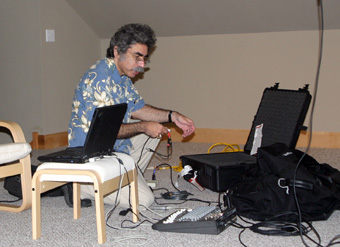
Armed with a case of equipment, a laptop, and a booklet of handwritten notes and diagrams, Terry arrived and was immediately in his element. As he set up his gear, he walked me through what measurements he would be taking and what he thought he could accomplish with the results. Room modes The room modeling was enlightening. Terry said that, using the information I’d supplied him, he’d calculated the first lengthwise and second widthwise room modes, which were significant and would have to be addressed early on. A room mode is the frequency at which a natural resonance of the room’s air occurs. It exerts its maximum pressure at the room boundaries, and forms a standing wave in between. The first room mode’s maximum pressure is just at the walls. The second room mode has an additional region of pressure halfway between the walls, and so on. Two such modes in my room -- the first at 27Hz, the second at 48Hz -- would be a bear to deal with due to their very low frequencies; basically, the lower the frequency, the more difficult it is to absorb with passive traps. There were several solutions offered to eradicate the first lengthwise mode. The easiest to implement would be to cross over my main speakers at around 38Hz with a high-pass filter, thereby avoiding the first lengthwise axial room mode of 27Hz. (An axial mode involves one dimension of the room, whereas a tangential mode involves two dimensions, and an oblique mode three dimensions.) In this arrangement I would be using my subwoofer to reproduce all bass frequencies below 38Hz. I could then employ my Wilson Audio Specialties WATCH Dog 2 subwoofer’s parametric equalizer to notch out the room mode. Of course, adding a crossover in line with my Alexandria X-2 loudspeakers was out of the question. As any card-carrying audiophile can attest, the signal path had to remain free of unnecessary electronics, and so this option never got off the ground. Before any more solutions were discussed, we decided to run a frequency-response measurement to confirm Terry’s modeled graphs. First round of measurements
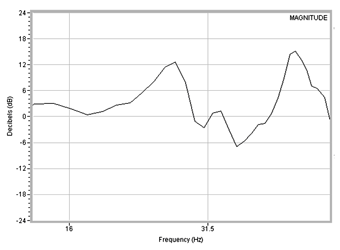
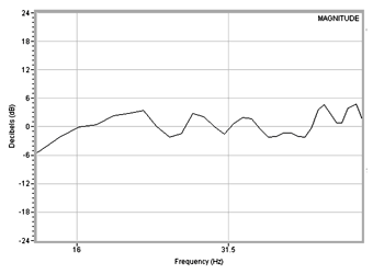
Terry’s first frequency-response graphs were plotted using pink noise and SIA SmaartLive software. (Pink noise is composed of equal energy per octave, whereas its counterpart, white noise, is equal energy per frequency. Although white noise is considered spectrally flat, pink noise is generally considered more pleasing to the ear because it more closely approximates the way we hear in real life.) Terry’s initial modeling was proven spot on by the results: my room’s 27Hz mode was evident as a 12.7dB peak in the graph. Discussing with Terry the thought of building a tuned bass trap that would address that mode revealed that the physical size of such a beast would be downright scary. Bass traps need to be larger as the frequency decreases because, in general, they scale with the wavelengths that they can absorb. Lower frequencies mean longer wavelengths, therefore bigger traps. This passive approach, although theoretically possible, would in practice be prohibitive. A third means of eradicating the 27Hz mode was called into service: active cancellation. With my Alexandria X-2s capable of floor-shaking bass down to 20Hz, the addition of the WATCH Dog 2 was all but superfluous. But the subwoofer could be used, according to Terry, to actively flatten my system’s bass response. This could be done by placing the sub in a high-pressure area of the mode while matching the level to the main speakers and finding the desired phase. Terry explains how this works: "The subwoofer phase was adjusted to be equal and opposite that of the mains. A sub’s low-pass filter will always introduce a frequency-dependent phase shift, so it was just a matter of searching for the right phase at the desired frequency." After setting the subwoofer, remeasuring, resetting, remeasuring, and so on, many times, we finally nailed the proper phase setting: 67.5 degrees. Sure enough, that 27Hz peak was now as flat as a calm lake. The secondary widthwise axial room mode was centered at 48Hz. To deal with this peak, Terry surmised that speaker placement would be critical. However, simply finding good positions for the speakers would ignore a critical aspect of the setup: Wilson Audio’s prescribed guidelines for speaker placement. One component of the company’s placement method dictates that the distance from the listener to each speaker’s tweeter be 1.1 to 1.25 times the distance from speaker to speaker. Terry had conferred with Wilson Audio’s John Giolas in a phone call the week before he arrived at my place, and had gathered from John the information he would need in order to take into account Wilson’s placement requirements. I can’t overstate how important this turned out to be. When choosing a designer for your room, make sure you have someone willing to take into consideration the specific equipment that will be used in the system, and plan for special circumstances, such as the speaker manufacturer’s placement guidelines.
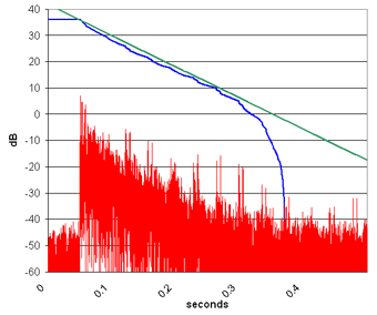
After mapping out the fairly limited range of placement options based on the Wilson Audio ratio, Terry went to work, calculating how the secondary widthwise axial mode could be canceled. Terry explains how, through placement, this was accomplished: "The secret here was to use the mode to our advantage. The second widthwise axial mode has its maximum pressure at the sidewalls and at the center line of the room -- in other words, at 0%, 50%, and 100% the width of the room. It has its pressure nulls at 25% and 75% of the room width. We placed the speakers at or near these points, which, for this room, was consistent with Wilson’s recommendations. When you put a speaker at the null of a room mode, it cannot be excited. The mode becomes a nonissue." The above exercise would provide valuable information come the final setup. All of the measurements would have to be repeated, and a final frequency-response graph generated, to verify that the flattest response possible had been attained. Treatment options Once the most significant room modes had been addressed through active cancellation and speaker-placement calculations, the other frequency-response deviations -- as well as a host of other acoustic issues -- could be ameliorated. These anomalies would be measured and documented, and then a plan would be laid out to passively treat them. As the frequency rises, passive absorption and diffusion become the solutions of choice for improving acoustics. The frequency-response graph revealed a host of peaks and dips that would need to be flattened for good sound, as well as many strong reflections off the walls and ceiling. But how do you determine what types of room treatment are needed and where they need to be placed? Absorbers and bass traps vary in thickness, material, shape, and size, and many different types and sizes of diffusers are available. I chose to have each passive treatment device custom-built for my room to Terry’s specifications. This is the most predictable way to ensure a perfect physical fit and the exact performance predicted by the engineer. Second round of measurements My room’s ratio of absorption to diffusion would be determined by, among other factors, the room’s reverberation time. The reverberation time is revealed by an impulse-response measurement. This was measured in the untreated room, and simulated using ray-tracing software. Terry explains: "The impulse response is exactly how the room responds to a pulse of sound. It is a decay curve of reverberation. As such, you can use it to directly calculate the reverberation time." How do you perform an impulse-response test? Terry: "Suppose we feed a known signal, A, into the room via a loudspeaker. We measure the result, R, from a microphone at a particular spot in the room. We mathematically subtract A from R to get X. Well, X is none other than the ‘signal’ of the room -- its impulse response! The signal can be anything that hits all the audible frequencies -- white noise, pink noise, or a sinewave sweep.
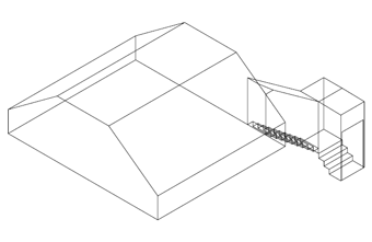
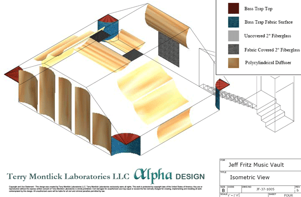
"Ray-tracing computer simulation uses a different principle to get the impulse response," explains Terry. "The room geometry is carefully modeled using a standard architectural CAD [computer-aided design] program, such as AutoCAD. We model each significant room feature to an accuracy of 0.5". This model is then fed into our acoustical ray-tracing software, which shoots out random ‘rays’ of sound in all directions from a speaker position, and records each ray’s arrival time at the listener, as well as its amplitude after reflecting (up to 40 times) off of room surfaces. Each room surface has been carefully characterized by a set of known absorption and diffusion coefficients. This data is recorded and built up over many thousands of rays. The result is the impulse response of the room. Now that we have reproduced the impulse response in the lab, we can simulate the effects of room treatments. And, as discussed in the previous installment of this article, the impulse response contains all the information we need to characterize the room." Reverberation time, taken from the impulse response, is presented in what is commonly referred to as an RT60 specification. In simple terms, the RT60 tells you how long it takes, in seconds, for the sound-pressure level in a room to decrease by 60dB. This measurement is done over octave frequency bands from 125Hz to 4000Hz. The higher the reverberation time, the more absorption you need. The lower the reverberation time, the more diffusion to address reflections. Optimizing the room My room is being optimized for two-channel sound, not surround sound. Therefore, the room’s acoustics would need to be tailored for two sources of sound, not five or seven. Terry explains: "We wanted to use a lot of diffusion in this room, and not an excessive amount of absorption. This keeps the room relatively ‘live’ so that sound comes from all directions. Diffusion smooths out the soundfield so that the room minimally colors the sound. "Schroeder diffusers are a very popular and effective choice. These diffusers have either various-depth wells or different-height raised surfaces. They diffuse sound via the phase interference produced by soundwaves when they reflect from these varying-depth surfaces. But I chose specifically not to go with Schroeder diffusers for this project. A little-known fact about these diffusers is that they inherently absorb a fair amount of sound over a wide range of frequencies. "Instead, I chose an oldie-but-goodie design: the classic polycylindrical diffuser. This diffuser doesn’t absorb sound like the Schroeder. It is a simple curved surface that diffuses sound by simply reflecting it in different directions when it bounces off different parts of the curve. I can’t claim originality here. I chose a polycylindrical design right out of a 1941 Journal of the Acoustical Society of America paper. ‘Polys’ also have the advantage of being easy to build. All you need to do is bend a piece of hard, reflective material, in this case, 1/8" Masonite. "Another treatment we used was a collection of custom bass traps for the corners. These would help for the low frequencies that we couldn’t control through speaker placement. The bass traps are half-round shapes, up to 34" in radius, filled with ordinary fiberglass batting. A simple facing of Kraft Paper would reflect and diffuse high frequencies, while freely passing the lower frequencies to be absorbed by the deep fiberglass."
Next time The final installment in this series will show you the finished room, the equipment setup, the final measurements, and will include my detailed listening impressions. ...Jeff Fritz
Ultra Audio is part of the SoundStage! Network. |

